Implementing simple interior mapping
Interior mapping
The technique isn't particularly new I think, but it gained a lot of traction in 2018, when Spiderman by Insomniac came out on PlayStation 4. It featured Manhatten and there are a loooooot of skyscarpers. So they needed a special way to efficiently render a lot of skyscrapers, of course in high fidelity. This post shows some screenshots of the feature and also describes how it is done. Since I played the game the very first time, of course it immediately popped into my eyes how they did it.
My Master's thesis
And I felt reminded of my Master's thesis, where I implemented a global illumination algorithm for realtime rendering based on localized cubemaps. The idea was to take a cubemap and project it onto a cube that approximates an area in your scene. Then resolve your scene's primary visibility, for example by rendering a g-buffer with deferred rendering. In the shading stage, calculate the global illumation by reflecting the view vector on the surface normal and intersect that one with our cubes. Depending on the roughness of the surface, select a mipmap - we don't need that step for interior mapping.
But what's more or less the same, is the actual box projection. But instead of tracing the reflection vector, we just trace the view vector, et voila, done. This can be implemented as a simple material like any other in your engine by calculating the output color of the pixel a bit differently.
In my own engine, I already have the axis aligned bounding box for every entity in the scene, I need that for culling already. If you want to support arbitrarily rotated cubes, of cource axis alignment is not sufficient. Additionally, every entity already has a material - when the material support dfinition for an environment map, we're almost there. What we need is the following addition for the fragment shader output:
// project the view vector onto the box, so that we can use the result to sample the box's cubemap
vec3 boxProjected = boxProject(eyePosition, V, entity.min, entity.max);
// I use this to randomize the rotation of the cubemap on y axis by multiples of 90 degrees
mat4 rotationMatrix = rotationMatrix(vec3(0,1,0), 1.57 * (entityId % 10));
vec3 newV = (rotationMatrix * vec4(boxProjected, 0)).xyz;
out_color.rgba = texture(environmentMap, newV);
Box projection is code that was already there, as I wrote, for my Master's thesis:
vec3 getIntersectionPoint(vec3 position_world, vec3 texCoords3d, vec3 environmentMapMin, vec3 environmentMapMax) {
    vec3 nrdir = normalize(texCoords3d);

    vec3 rbmax = (environmentMapMax - position_world.xyz)/nrdir;
    vec3 rbmin = (environmentMapMin - position_world.xyz)/nrdir;
    //vec3 rbminmax = (nrdir.x > 0 && nrdir.y > 0 && nrdir.z > 0) ? rbmax : rbmin;
    vec3 rbminmax;
    rbminmax.x = (nrdir.x>0.0)?rbmax.x:rbmin.x;
    rbminmax.y = (nrdir.y>0.0)?rbmax.y:rbmin.y;
    rbminmax.z = (nrdir.z>0.0)?rbmax.z:rbmin.z;
    float fa = min(min(rbminmax.x, rbminmax.y), rbminmax.z);
    vec3 posonbox = position_world.xyz + nrdir*fa;

    return posonbox;
}
vec3 boxProject(vec3 position_world, vec3 texCoords3d, vec3 environmentMapMin, vec3 environmentMapMax) {
    vec3 posonbox = getIntersectionPoint(position_world, texCoords3d, environmentMapMin, environmentMapMax);

    vec3 environmentMapWorldPosition = environmentMapMin + (environmentMapMax - environmentMapMin)/2.0;

    return normalize(posonbox - environmentMapWorldPosition.xyz);
}
It's not much more than finding the intersection point of the view vector and the box first. Then, we construct a vector from the center of the cube to that intersection point and we have what we need to sample the cubemap.
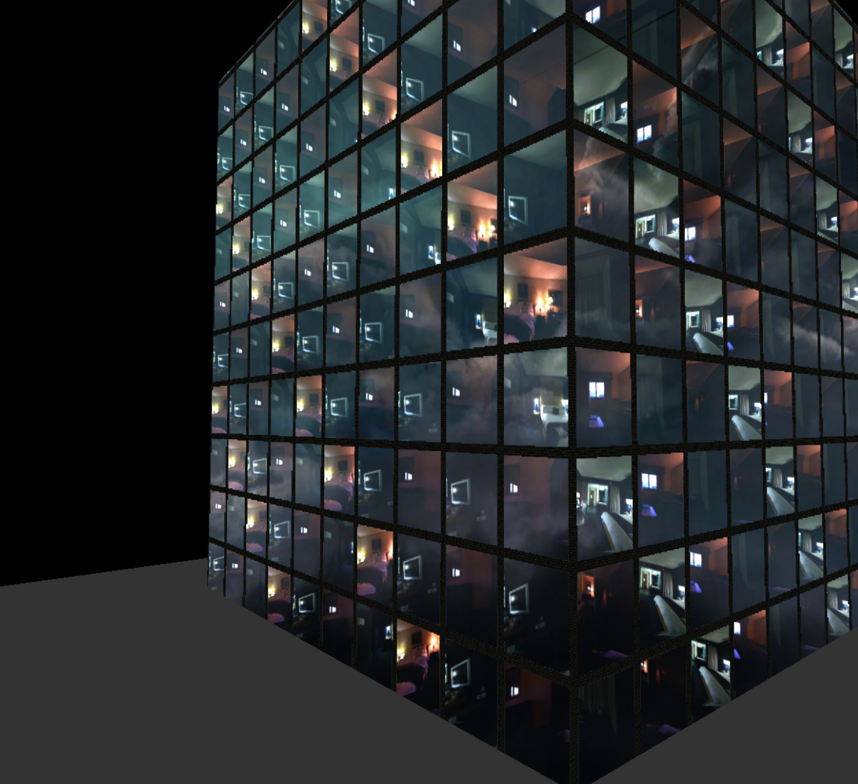
Building a skyscraper
So much for a single box - but a skyscraper doesn't consist of a single box. It consists of hundrets of them. In the post linked above, you can see how a big plane was used to fake even the box geometry, so simply everything. A different way to create a building is by instancing a lot of those cubes, simply. The geometry can of course be reused and only uplaoded once. What needs to be per instance is the translation and a cubemap. Because you want to have different rooms, not 100 times the same room. In my case, I haven't even used instancing, I just created 200 entities - since I do programmable vertex pulling and use entity ids to pull instance data from a big shared buffer, it doesn't really matter for me exactly. The only thing that I probably need to take care of is culling: Since every room is an entity, it is culled on the cpu already. That has upsides and downsides, but for now I did it like that because it's super simple.
Additionally, I create the vertical and horizontal brick planes for the building seperately. Normally, one would do that in a nicer way. I also needed much more time to get their placement right than I did for getting the actual interior mapping done ... Because I needed to implement worldspace UVs, and of course for variable axises.
I used two cubemaps from hummus, basically the only two that are interiors. Rotated them a bit and randomized the indices the rooms actually use. Given that small amount of data, it already looks quite convincing.
Recording eats up some of the fps - but even on a laptop gpu (AMD 780M) this fairly inefficient implementation can render at multiple hundrets frames per second.
Keep in mind that there is an important difference between what I do and what the technique by Insomniac: I project a cube (the room) onto a sphere, because that's what most cubemap textures are and that's what I needed for my thesis. If you can prepare your cubemaps so that they are literally cube environments that can be better projected onto a cube, like in Spiderman, than that would of course be recommended. One can see in the linked post above how such data looks (better).
Tracing plane geometry only
The above described implementation allthough simple, would (probably) be very costly in central Manhatten. Imagine you have 12 triangles per cube, so per window. Given 40 windows per floor and 40 floors per building, it's already 1600 triangles per building. Instead of 8, as in 4 planes for the building's 4 sides. Using the traditional approach, we can reduce vertices by a lot. So let's go.
Our geometry is now only two planes, positioned in a 45° angle.
The fragment shader first takes the boundaries of our plane mesh and subdivides it in n cells.
vec3 entityMin = entity.min;
vec3 entityMax = entity.max;
int cellCount = 10;
ivec3 cellSize = ivec3((entityMax - entityMin).xy/float(cellCount), 110);
if(isZYPlane) {
    cellSize = ivec3(110, (entityMax - entityMin).yz/float(cellCount));
}
This only works when we know which plane we are talking about. For now, I support xy and zy planes. I also only support aabb for bounding volumes in my engine. The depth of the cell gets a default value, arbitrary, because, you know, a plane doesn't have any depth, it's faked.
Afterwards, we can use the world position of the fragment to calculate the cell index the shader execution is in.
ivec3 indices = ivec3((position_world.xyz - entityMin)/cellSize);
int index = indices.x + indices.y + indices.z;

vec3 min = entityMin + indices * cellSize;
vec3 max = min + cellSize;
// for the given plane, i have to invert z, i guess it's because opengl coordinates are -z is camera view direction
// but i am not completely sure, need to investigate, but won't work without this
if(isXYPlane) {
    V.z *= -1;
}
vec3 newV = boxProjectFar(position_world.xyz, V, min, max);
// we rotate the vector a bit randomly around 45° so that we get some variation in our rooms
mat4 rotationMatrix = rotationMatrix(vec3(0,1,0), 1.57 * (index % 10));
newV = (rotationMatrix * vec4(newV, 0)).xyz;
The newV vector can be used for sampling the cubemap directly. What happens in boxProjectFar is determining the intersection points between view vector and our cell aabb and pick the one that's farther away.
// from https://gist.github.com/DomNomNom/46bb1ce47f68d255fd5d
vec2 intersectAABB(vec3 rayOrigin, vec3 rayDir, vec3 boxMin, vec3 boxMax) {
    vec3 tMin = (boxMin - rayOrigin) / rayDir;
    vec3 tMax = (boxMax - rayOrigin) / rayDir;
    vec3 t1 = min(tMin, tMax);
    vec3 t2 = max(tMin, tMax);
    float tNear = max(max(t1.x, t1.y), t1.z);
    float tFar = min(min(t2.x, t2.y), t2.z);
    return vec2(tNear, tFar);
}
vec3 boxProjectFar(vec3 position_world, vec3 texCoords3d, vec3 environmentMapMin, vec3 environmentMapMax) {
    vec3 posonbox = position_world + texCoords3d * intersectAABB(position_world, texCoords3d, environmentMapMin, environmentMapMax).y;
    vec3 environmentMapWorldPosition = environmentMapMin + (environmentMapMax - environmentMapMin)/2.0;
    return normalize(posonbox - environmentMapWorldPosition.xyz);
}
Now we need to tell which fragment should be the concrete or brick part of the fassade and which is actual window glass.
vec3 positionInCell = (ivec3(position_world.xyz - entityMin)%ivec3(cellSize)) + fract(position_world.xyz);
float windowBorderSize = cellSize.x - 5;
if(isXZPlane) {
    windowBorderSize = cellSize.z - 5;
}

bool isWindow = (positionInCell.x > 5 && positionInCell.x < windowBorderSize)
    && (positionInCell.y > 5 && positionInCell.y < windowBorderSize);
if(material.worldSpaceTexCoords == 2) {
    isWindow = (positionInCell.z > 5 && positionInCell.z < windowBorderSize)
        && (positionInCell.y > 5 && positionInCell.y < windowBorderSize);
}

if(isWindow) {
    // sample our cubemap
    out_color.rgba = vec4(texture(index%2 == 0 ? environmentMap : environmentMap0, newV).rgb, 1);

    // blend skybox cubemap on top of it
    vec3 boxProjectedV = boxProjectFar(position_world.xyz, reflect(V, normal_world), vec3(-2000), vec3(2000));
    out_color.rgb += (1-material.roughness) * texture(environmentMap1, boxProjectedV).rgb;
} else {
    if(material.worldSpaceTexCoords == 2) {
        out_color.rgba = vec4(texture(normalMap, position_world.zy * 0.05).rgb, 1);
    } else {
        out_color.rgba = vec4(texture(normalMap, position_world.xy * 0.05).rgb, 1);
    }
}
For sampling the brick texture, we can use scaled world space positions as texture coordinates. For the glass, we can blend a reflection on top of it - the skybox, also projected onto a big box so that the reflection moves nicely when moving the camera.
When instead of a cubemap we would like to sample form a bunch of 2D textures for floors, walls, ceilings distincively, it would be achieved by this code:
uint dominantAxis = getDominantAxis(newV);
vec2 uv;
if(dominantAxis == 0) {
    uv = (vec2(-newV.z, -newV.y)/abs(newV.x)+vec2(1))/2;
} else if(dominantAxis == 1) {
    uv = (vec2(-newV.x, newV.z)/abs(newV.y)+vec2(1))/2;
} else {
    uv = (vec2(-newV.x, newV.y)/abs(newV.z)+vec2(1))/2;
}
This way, permutations would be easier to achieve for a lot of cells.
Finally, here's a video of this implementation as well:
Closing words
At the beginning, I thought it would be much easier for me to implement interior mapping by just having box geometry and use my existing box projection. That was true, but only for a single box. When I tried to assemble a whole building block, it took me way too long to programmatically position all the boxes, all the brick planes, the wholes for the windows, the glass panes. Implementing all that stuff in a fat fragment shader was much simpler in the end. So the traditional implementation not only performs better, it's also simpler to implement. If I will ever be able to find out why I have to invert z at this one place in the code, I would be happy. Or when I support non axis aligned planes as well. Or when I find nice textures so that switching from whole cubemaps to 2D textures gives me some nice demo scene to render.
Other than that, funny experiment. Impressive how simple ideas can make such a difference in immersion.